ESP32 + SH1106 OLED + EC11エンコーダ 開発ガイド
## 概要
このドキュメントは、ESP32でSH1106 OLEDディスプレイとEC11ロータリーエンコーダを使用するための完全なガイドです。
### 対象ハードウェア
| 項目 | 型番/仕様 |
|------|----------|
| マイコン | ESP-WROOM-32 |
| ディスプレイ | SH1106 1.3インチ OLED (I2C, 128x64) |
| エンコーダ | EC11 ロータリーエンコーダ |
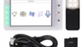
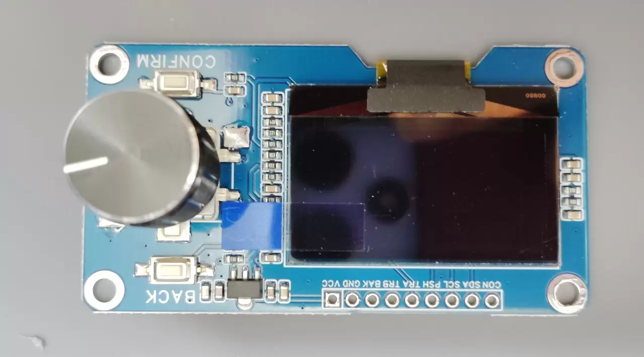
| モジュール | Estardyn OLEDモジュール(SH1106ドライバ/EC11エンコーダ統合) |
---
## ハードウェア
### ピン接続
| モジュール側 | ESP32 | 機能 |
|-------------|-------|------|
| VCC (3V3-5V) | 3.3V | 電源 |
| GND | GND | グランド |
| OLED_SDA | GPIO21 | I2Cデータ |
| OLED_SCL | GPIO22 | I2Cクロック |
| ENCODER_TRA | GPIO32 | エンコーダA相 |
| ENCODER_TRB | GPIO33 | エンコーダB相 |
| ENCODER_PUSH | GPIO25 | エンコーダ押しボタン |
| CONFIRM | GPIO26 | 確認ボタン |
| BAK (BACK) | GPIO27 | 戻るボタン |
### 回路図
ESP32 モジュール ┌─────────┐ ┌─────────────┐ │ 3.3V├──────────────┤VCC │ │ GND├──────────────┤GND │ │ GPIO21├──────────────┤OLED_SDA │ │ GPIO22├──────────────┤OLED_SCL │ │ GPIO32├──────────────┤ENCODER_TRA │ │ GPIO33├──────────────┤ENCODER_TRB │ │ GPIO25├──────────────┤ENCODER_PUSH │ │ GPIO26├──────────────┤CONFIRM │ │ GPIO27├──────────────┤BAK │ └─────────┘ └─────────────┘
### ボタンの動作

すべてのボタンはプルアップ接続です。

| 状態 | 電圧 | digitalRead() |
|------|------|---------------|
| 押していない | HIGH (3.3V) | 1 |
| 押している | LOW (0V) | 0 |

### エンコーダの動作

EC11は2相(A相、B相)のインクリメンタルエンコーダです。
時計回り(CW)の波形: A相: ▁▁▁▔▔▔▁▁▁▔▔▔ B相: ▔▔▁▁▁▔▔▔▁▁▁▔ ↑ A相立ち上がり時、B相はLOW
反時計回り(CCW)の波形: A相: ▁▁▁▔▔▔▁▁▁▔▔▔ B相: ▁▁▔▔▔▁▁▁▔▔▔▁ ↑ A相立ち上がり時、B相はHIGH
1クリック(デテント)で4つの状態遷移が発生します(4逓倍)。

---

## ソフトウェア

### 必要なライブラリ

Arduino IDEのライブラリマネージャからインストールしてください。

| ライブラリ | 用途 | 備考 |
|-----------|------|------|
| U8g2 | OLED表示 | SSD1306用ライブラリは使用不可 |

### 対応Arduino Coreバージョン

| バージョン | PCNT API | 対応状況 |
|-----------|----------|----------|
| 2.x系 | driver/pcnt.h | ✅ 対応 |
| 3.x系 | driver/pulse_cnt.h | ✅ 対応 |

コード内で`ESP_ARDUINO_VERSION_MAJOR`マクロにより自動判定します。

### OLEDディスプレイ

#### 初期化

```cpp
#include <U8g2lib.h>
#include <Wire.h>

// SH1106 128x64 I2C (アドレス: 0x3C)
U8G2_SH1106_128X64_NONAME_F_HW_I2C u8g2(U8G2_R0, U8X8_PIN_NONE);

void setup() {
  u8g2.begin();
}
注意点
- SSD1306ライブラリは使用不可: SH1106とSSD1306は互換性がありません
- 画面がおかしい場合はドライバICを確認してください
- I2Cアドレスは通常0x3C(0x3Dの場合もあり)
基本的な描画
Copyvoid loop() {
  u8g2.clearBuffer();                 // バッファクリア
  u8g2.setFont(u8g2_font_ncenB14_tr); // フォント設定
  u8g2.setCursor(0, 20);              // カーソル位置
  u8g2.print("Hello!");               // 文字描画
  u8g2.sendBuffer();                  // 画面に転送
}
よく使うフォント
| フォント名 | サイズ | 用途 |
|---|---|---|
| u8g2_font_5x7_tr | 極小 | 詳細情報 |
| u8g2_font_6x10_tr | 小 | ステータス表示 |
| u8g2_font_ncenB08_tr | 中 | 通常テキスト |
| u8g2_font_ncenB14_tr | 大 | タイトル、数値 |
| u8g2_font_ncenB18_tr | 特大 | メイン表示 |
エンコーダ読み取り方式
2つの方式があります。用途に応じて選択してください。
方式1: 割り込み方式
特徴
- シンプルで理解しやすい
- どのESP32でも動作
- CPUを少し使用(エンコーダ程度なら問題なし)
- 移植性が高い
実装
#define ENC_A 32
#define ENC_B 33

volatile int rawCount = 0;

void IRAM_ATTR encISR() {
  static uint8_t lastAB = 0;

  uint8_t a = digitalRead(ENC_A);
  uint8_t b = digitalRead(ENC_B);
  uint8_t ab = (a << 1) | b;

  // 状態遷移テーブル
  static const int8_t trans[] = {
     0, -1,  1,  0,
     1,  0,  0, -1,
    -1,  0,  0,  1,
     0,  1, -1,  0
  };

  rawCount += trans[(lastAB << 2) | ab];
  lastAB = ab;
}

void setup() {
  pinMode(ENC_A, INPUT_PULLUP);
  pinMode(ENC_B, INPUT_PULLUP);
  attachInterrupt(ENC_A, encISR, CHANGE);
  attachInterrupt(ENC_B, encISR, CHANGE);
}

int getEncoderValue() {
  noInterrupts();
  int raw = rawCount;
  interrupts();

  // 4逓倍なので4で割る
  if (raw >= 0) {
    return raw / 4;
  } else {
    return (raw - 3) / 4;
  }
}
方式2: PCNT方式(推奨)
特徴
- CPU負荷ゼロ(ハードウェアカウント)
- ハードウェアグリッチフィルタ内蔵
- 高速回転でも取りこぼさない
- オーバーフロー対応可能
- Arduino Coreバージョンで API が異なる
2.x/3.x両対応の完全な実装は「完全なサンプルコード」セクションを参照
PCNT設定パラメータ
2.x系 pcnt_config_t
| パラメータ | 説明 | 設定例 |
|---|---|---|
| pulse_gpio_num | パルス入力ピン | ENC_A または ENC_B |
| ctrl_gpio_num | 制御ピン | ENC_B または ENC_A |
| pos_mode | 立ち上がりエッジの動作 | PCNT_COUNT_INC |
| neg_mode | 立ち下がりエッジの動作 | PCNT_COUNT_DEC |
| lctrl_mode | 制御ピンLOW時の動作 | PCNT_MODE_KEEP/REVERSE |
| hctrl_mode | 制御ピンHIGH時の動作 | PCNT_MODE_REVERSE/KEEP |
| counter_h_lim | カウンタ上限 | 10000 |
| counter_l_lim | カウンタ下限 | -10000 |
4逓倍の正しい設定
Copy// チャンネル0: A相のエッジを検出
config0.pulse_gpio_num = ENC_A;
config0.ctrl_gpio_num  = ENC_B;
config0.lctrl_mode     = PCNT_MODE_KEEP;
config0.hctrl_mode     = PCNT_MODE_REVERSE;
config0.pos_mode       = PCNT_COUNT_INC;
config0.neg_mode       = PCNT_COUNT_DEC;

// チャンネル1: B相のエッジを検出
config1.pulse_gpio_num = ENC_B;
config1.ctrl_gpio_num  = ENC_A;
config1.lctrl_mode     = PCNT_MODE_REVERSE;  // ←ここが逆
config1.hctrl_mode     = PCNT_MODE_KEEP;     // ←ここが逆
config1.pos_mode       = PCNT_COUNT_INC;
config1.neg_mode       = PCNT_COUNT_DEC;
重要: チャンネル0とチャンネル1でlctrl_modeとhctrl_modeが入れ替わります。これを間違えるとカウントが打ち消し合います。
値の変換
raw値からエンコーダ値への変換
4逓倍なので4で割りますが、負の値の割り算に注意が必要です。
Copyint32_t rawToEnc(int32_t raw) {
  if (raw >= 0) {
    return raw / 4;
  } else {
    // 負の値は調整しないと0を2回通過する
    return (raw - 3) / 4;
  }
}
| raw値 | 通常の/4 | 修正後 |
|---|---|---|
| 4 | 1 | 1 |
| 3 | 0 | 0 |
| 0 | 0 | 0 |
| -1 | 0 | -1 |
| -4 | -1 | -1 |
| -5 | -1 | -2 |
完全なサンプルコード
デバッグツール(PCNT方式、2.x/3.x両対応、オーバーフロー対応)
Copy/*
 * ============================================================
 * PCNT ロータリーエンコーダ デバッグツール
 * Version: 7 (Final)
 * ============================================================
 */

#include <U8g2lib.h>
#include <Wire.h>

#if ESP_ARDUINO_VERSION_MAJOR >= 3
  #include "driver/pulse_cnt.h"
  #define USE_NEW_PCNT_API
#else
  #include "driver/pcnt.h"
#endif

#define VERSION "v7"

U8G2_SH1106_128X64_NONAME_F_HW_I2C u8g2(U8G2_R0, U8X8_PIN_NONE);

#define ENC_A    32
#define ENC_B    33
#define ENC_BTN  25
#define CONFIRM  26
#define BACK     27

#define PCNT_H_LIM  10000
#define PCNT_L_LIM -10000
#define GLITCH_FILTER_NS 1000
#define GLITCH_FILTER_CLK 100

volatile int32_t overflowCount = 0;
int32_t encValue = 0;
int32_t lastFullCount = 0;

#ifdef USE_NEW_PCNT_API
  pcnt_unit_handle_t pcntUnit = NULL;

  bool pcntCallback(pcnt_unit_handle_t unit, const pcnt_watch_event_data_t *edata, void *ctx) {
    if (edata->watch_point_value == PCNT_H_LIM) {
      overflowCount++;
    } else if (edata->watch_point_value == PCNT_L_LIM) {
      overflowCount--;
    }
    return false;
  }
#else
  #define PCNT_UNIT PCNT_UNIT_0

  void IRAM_ATTR pcntISR(void *arg) {
    uint32_t status = 0;
    pcnt_get_event_status(PCNT_UNIT_0, &status);
    if (status & PCNT_EVT_H_LIM) overflowCount++;
    if (status & PCNT_EVT_L_LIM) overflowCount--;
  }
#endif

bool setupPCNT() {
#ifdef USE_NEW_PCNT_API
  pcnt_unit_config_t unitConfig = {
    .low_limit = PCNT_L_LIM,
    .high_limit = PCNT_H_LIM,
  };

  if (pcnt_new_unit(&unitConfig, &pcntUnit) != ESP_OK) return false;

  pcnt_glitch_filter_config_t filterConfig = { .max_glitch_ns = GLITCH_FILTER_NS };
  pcnt_unit_set_glitch_filter(pcntUnit, &filterConfig);

  pcnt_chan_config_t chanAConfig = { .edge_gpio_num = ENC_A, .level_gpio_num = ENC_B };
  pcnt_channel_handle_t chanA = NULL;
  pcnt_new_channel(pcntUnit, &chanAConfig, &chanA);
  pcnt_channel_set_edge_action(chanA, PCNT_CHANNEL_EDGE_ACTION_INCREASE, PCNT_CHANNEL_EDGE_ACTION_DECREASE);
  pcnt_channel_set_level_action(chanA, PCNT_CHANNEL_LEVEL_ACTION_KEEP, PCNT_CHANNEL_LEVEL_ACTION_INVERSE);

  pcnt_chan_config_t chanBConfig = { .edge_gpio_num = ENC_B, .level_gpio_num = ENC_A };
  pcnt_channel_handle_t chanB = NULL;
  pcnt_new_channel(pcntUnit, &chanBConfig, &chanB);
  pcnt_channel_set_edge_action(chanB, PCNT_CHANNEL_EDGE_ACTION_INCREASE, PCNT_CHANNEL_EDGE_ACTION_DECREASE);
  pcnt_channel_set_level_action(chanB, PCNT_CHANNEL_LEVEL_ACTION_INVERSE, PCNT_CHANNEL_LEVEL_ACTION_KEEP);

  pcnt_unit_add_watch_point(pcntUnit, PCNT_H_LIM);
  pcnt_unit_add_watch_point(pcntUnit, PCNT_L_LIM);

  pcnt_event_callbacks_t callbacks = { .on_reach = pcntCallback };
  pcnt_unit_register_event_callbacks(pcntUnit, &callbacks, NULL);

  pcnt_unit_enable(pcntUnit);
  pcnt_unit_clear_count(pcntUnit);
  pcnt_unit_start(pcntUnit);
  return true;

#else
  pcnt_config_t config0 = {};
  config0.pulse_gpio_num = ENC_A;
  config0.ctrl_gpio_num  = ENC_B;
  config0.lctrl_mode     = PCNT_MODE_KEEP;
  config0.hctrl_mode     = PCNT_MODE_REVERSE;
  config0.pos_mode       = PCNT_COUNT_INC;
  config0.neg_mode       = PCNT_COUNT_DEC;
  config0.counter_h_lim  = PCNT_H_LIM;
  config0.counter_l_lim  = PCNT_L_LIM;
  config0.unit           = PCNT_UNIT_0;
  config0.channel        = PCNT_CHANNEL_0;
  if (pcnt_unit_config(&config0) != ESP_OK) return false;

  pcnt_config_t config1 = {};
  config1.pulse_gpio_num = ENC_B;
  config1.ctrl_gpio_num  = ENC_A;
  config1.lctrl_mode     = PCNT_MODE_REVERSE;
  config1.hctrl_mode     = PCNT_MODE_KEEP;
  config1.pos_mode       = PCNT_COUNT_INC;
  config1.neg_mode       = PCNT_COUNT_DEC;
  config1.counter_h_lim  = PCNT_H_LIM;
  config1.counter_l_lim  = PCNT_L_LIM;
  config1.unit           = PCNT_UNIT_0;
  config1.channel        = PCNT_CHANNEL_1;
  if (pcnt_unit_config(&config1) != ESP_OK) return false;

  pcnt_set_filter_value(PCNT_UNIT, GLITCH_FILTER_CLK);
  pcnt_filter_enable(PCNT_UNIT);

  pcnt_event_enable(PCNT_UNIT, PCNT_EVT_H_LIM);
  pcnt_event_enable(PCNT_UNIT, PCNT_EVT_L_LIM);
  pcnt_isr_service_install(0);
  pcnt_isr_handler_add(PCNT_UNIT, pcntISR, NULL);

  pcnt_counter_pause(PCNT_UNIT);
  pcnt_counter_clear(PCNT_UNIT);
  pcnt_counter_resume(PCNT_UNIT);
  return true;
#endif
}

int32_t getFullCount() {
#ifdef USE_NEW_PCNT_API
  int rawCount = 0;
  if (pcntUnit != NULL) pcnt_unit_get_count(pcntUnit, &rawCount);
  return (overflowCount * PCNT_H_LIM) + rawCount;
#else
  int16_t rawCount = 0;
  pcnt_get_counter_value(PCNT_UNIT, &rawCount);
  return (overflowCount * PCNT_H_LIM) + rawCount;
#endif
}

void clearCount() {
#ifdef USE_NEW_PCNT_API
  if (pcntUnit != NULL) pcnt_unit_clear_count(pcntUnit);
#else
  pcnt_counter_clear(PCNT_UNIT);
#endif
  overflowCount = 0;
}

int32_t rawToEnc(int32_t raw) {
  if (raw >= 0) return raw / 4;
  else return (raw - 3) / 4;
}

void setup() {
  Serial.begin(115200);
  delay(500);

  Serial.println("============================================");
  Serial.print("PCNT エンコーダ デバッグツール ");
  Serial.println(VERSION);
  Serial.println("============================================");

  pinMode(ENC_BTN, INPUT_PULLUP);
  pinMode(CONFIRM, INPUT_PULLUP);
  pinMode(BACK, INPUT_PULLUP);

  if (!setupPCNT()) {
    Serial.println("PCNT初期化失敗!");
    while (1) delay(1000);
  }

  u8g2.begin();
  Serial.println("準備完了!");
}

void loop() {
  int32_t fullCount = getFullCount();
  encValue = rawToEnc(fullCount);

  int pinA = digitalRead(ENC_A);
  int pinB = digitalRead(ENC_B);
  int btnEnc = digitalRead(ENC_BTN);
  int btnConf = digitalRead(CONFIRM);
  int btnBack = digitalRead(BACK);

  if (fullCount != lastFullCount) {
    Serial.print("raw:");
    Serial.print(fullCount);
    Serial.print(" enc:");
    Serial.print(encValue);
    Serial.print(" ovf:");
    Serial.println(overflowCount);
    lastFullCount = fullCount;
  }

  u8g2.clearBuffer();
  u8g2.setFont(u8g2_font_6x10_tr);
  u8g2.drawStr(0, 10, "[PCNT]");
#ifdef USE_NEW_PCNT_API
  u8g2.drawStr(40, 10, "3.x");
#else
  u8g2.drawStr(40, 10, "2.x");
#endif
  u8g2.drawStr(60, 10, "4x");
  u8g2.drawStr(80, 10, VERSION);

  u8g2.setFont(u8g2_font_ncenB14_tr);
  u8g2.setCursor(35, 30);
  u8g2.print(encValue);

  u8g2.setFont(u8g2_font_5x7_tr);
  u8g2.setCursor(0, 42);
  u8g2.print("raw:");
  u8g2.print(fullCount);
  u8g2.print(" ovf:");
  u8g2.print(overflowCount);

  u8g2.setCursor(0, 52);
  u8g2.print("A:");
  u8g2.print(pinA);
  u8g2.print(" B:");
  u8g2.print(pinB);

  u8g2.setCursor(0, 62);
  u8g2.print("E:");
  u8g2.print(btnEnc == LOW ? "*" : "-");
  u8g2.print(" C:");
  u8g2.print(btnConf == LOW ? "*" : "-");
  u8g2.print(" B:");
  u8g2.print(btnBack == LOW ? "*" : "-");

  u8g2.sendBuffer();

  if (btnEnc == LOW) {
    clearCount();
    Serial.println("リセット!");
    delay(200);
  }

  delay(10);
}
トラブルシューティング
OLEDが表示されない
| 症状 | 原因 | 対処 |
|---|---|---|
| 何も表示されない | I2C接続不良 | SDA/SCL配線確認、I2Cスキャンでアドレス確認 |
| ランダムなドット | ドライバIC違い | SSD1306ではなくSH1106用ライブラリを使用 |
| 画面がずれる | 解像度設定違い | 128×64を確認 |
I2Cアドレススキャン
Copyvoid scanI2C() {
  Serial.println("I2Cスキャン中...");
  for (byte addr = 1; addr < 127; addr++) {
    Wire.beginTransmission(addr);
    if (Wire.endTransmission() == 0) {
      Serial.print("発見: 0x");
      Serial.println(addr, HEX);
    }
  }
}
エンコーダが動かない
| 症状 | 原因 | 対処 |
|---|---|---|
| 全く反応しない | ピン接続間違い | A/Bピンの配線確認 |
| 値が増減しない | PCNT設定ミス | 2チャンネルのlctrl/hctrl設定確認 |
| 値が打ち消し合う | チャンネル設定が同じ | ch0とch1でlctrl/hctrlを入れ替える |
| チャタリング | フィルタ不足 | フィルタ値を増やす |
PCNTが動かない(3.x系)
エラー: driver/pcnt.h: No such file or directory
→ 3.x系ではdriver/pulse_cnt.hを使用してください。
Stack smashing protect failure!
バッファオーバーフローです。sprintfのバッファサイズを確認するか、u8g2.print()を使用してください。
Copy// NG: バッファ溢れの可能性
char buf[16];
sprintf(buf, "A:%d B:%d tot:%d", a, b, total);

// OK: 安全
u8g2.print("A:");
u8g2.print(a);
u8g2.print(" B:");
u8g2.print(b);
参考リンク
更新履歴
| バージョン | 日付 | 内容 |
|---|---|---|
| v1-v4 | – | デバッグ・調整 |
| v5 | – | 4逓倍動作確認 |
| v6 | – | オーバーフロー対応追加 |
| v7 | – | 2.x/3.x両対応、最終版 |